
Team PAYNTRIX 2010 Hovercraft Challenge entry
Welcome to my hovercraft design studio
Hull 2 Specification
| Length: | 1000mm | |
| Width: | 500mm | |
| Height: | 498mm | |
| Weight: | 13,500g | |
| Weight distribution: | ||
| Across width of craft | 2g to right (0.01%) | |
| Across length of craft | 300g to rear (2%) | |
| Lift: | Leaf Blower | |
| McCulloch | ||
| Air Stream IV | ||
| 21cc | ||
| Thrust: | Strimmer | |
| Spear and Jackson | ||
| 33cc | ||
| Prop options | 16 x 10 triple blade | Master Airscrew |
| 16 x 8 triple blade | Wooden | |
| 14 x 7 triple blade | Master Airscrew |
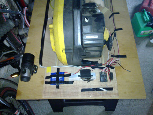
To balance the weight as much as possible, all the electronics and hovercam have been moved to the very front of the craft
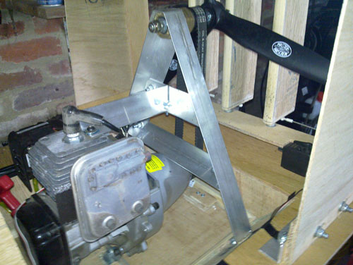
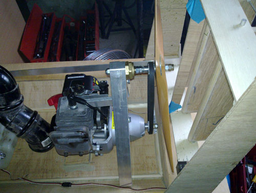
To ensure consistant belt tension an additional cross member has been added to the A frame to lock the relationship between the clutch housing (and therefore output shaft) and the prop drive shaft
And following Bobby Dazzler's agressive driving a few repairs have been made to the skirt. while the skirt was off, I rounded off the corners of the hull too.
Following the successful build and trials of hull 1 it was clear that improvements could be made to maximise performance.
Key areas that have been addresed are weight distribution, thrust, new air tube, new skirt
Here's a short video showing the new lift arrangement and how stable it is. Of course the rudders need attaching (although they are built) and the new pulleys. Oh and I will round the corners off on the hull.... See below for the work completed on the hull (under the video)
It can be seen from the video that the hull was wallowing on turning. This was partially due to the air tube being dislodged and venting some bag pressure, but it was mainly due to the very high centre of gravity.
The only way to improve this was by lowering the engines into the hull. Hull 2 was designed on the back of the success of Hull 1 and the knowledge gained from the initial trials.
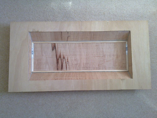
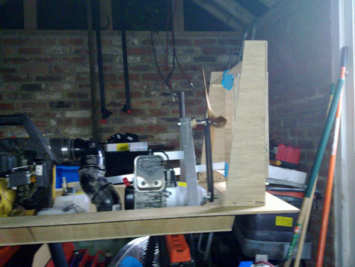
Hull 2 is now a single deck, V shaped hull which will allow the engines to be mounted as low as possible.
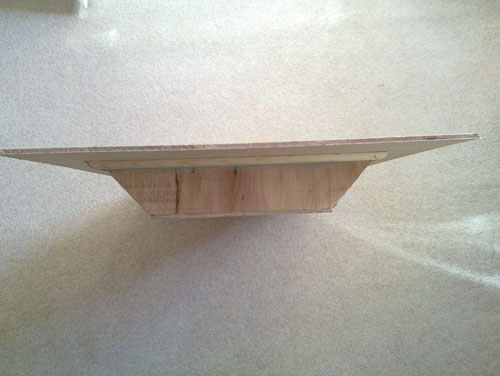
This does introduce an issue with the current thrust engine configuration. (See thrust)
This revised hull is lighter than Hull 1 by over 500grams despite being made solely from 6mm ply. The elimination of bulkheads and overlapping surfaces has enabled this weight saving.
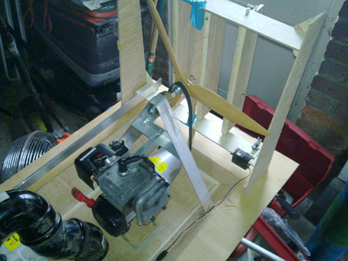
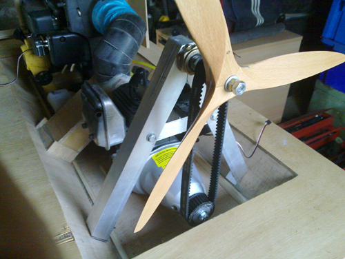
The original thrust configuration had the prop directly mounted to the output shaft of the thrust engine. By mounting the thrust engine directly to the base of the V hull, a drive system must be employed to raise the output drive shaft. A selection of pulleys and timing belts have been introduced to achieve this.
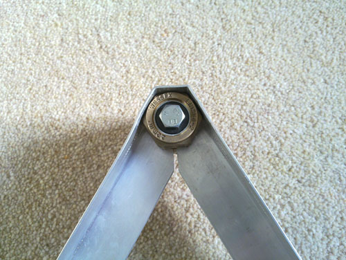
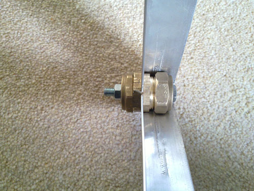
Firstly a set of bearings are required for the output shaft and a support frame. The support frame is made from aluminium angle and the bearing support from a 22mm compression fitting. The bearings are skateboard wheel bearings to support the 8mm shaft, and having a 22mm outside diameter fit perfectly into the pipe fitting.
Once the output shaft is in place the pulleys and belt have been added.
In the original configuration the craft generated 2.7KG of thrust. The change to a belt system allowed the opportunity to increase this. A 32 teeth lower pulley and 20 tooth output pulley should see maximum revs raise from 8,000 rpm to 12,800 rpm. Coupled with this I have obtained a larger prop going from a 14" x 7" to a mighty 16" x 8".
The projected thrust is in the region of 5KG, that should do it !
The larger prop has introduced size issues.
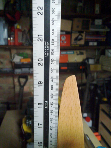
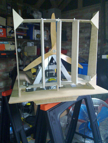
The 500mm height limit is dangerously close, and the A frame will be adjusted to allow space for a safety cage around the prop.
The original steering frame has suffered a triple blow. Firstly suffering central strut damage when I rolled hull 1 in the Matalan car park, secondly being shut in the garage door when the workmate was slightly too close to the door, and thirdly it is now not wide enough to accommodate the larger prop. So a revised frame will be made, although the rudders and servo link system are perfect and will be retained.
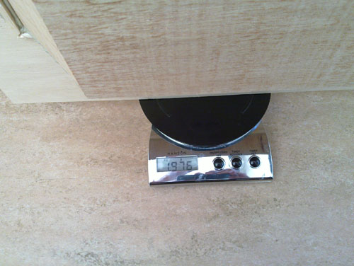
Lowering of the engine into the V of the hull was improved by removing the fuel tank too. This has allowed me to re-distribute the weight of the tank plus fuel to a better location, and also lightened the engine. I also removed all the covers and protective plates.
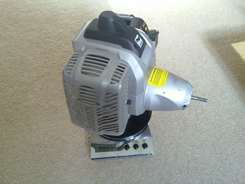
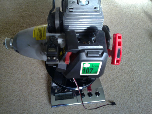
The loss of 300grams for the covers drops the weight from nearly 4Kg to 3.6Kg. Additionally removing the fuel tank (250g when empty) has also helped move the weight towards the desirable central position.
The exhaust on the engine has been changed too. The original orientation saw the exhaust gasses being blown forwards towards the lift engine. Once in the lower position the exit pipe was inside the V of the hull. I have turned the exhaust upside down so it now points backwards and is raised up out of the hull.
Update 09/04/10
The first H2 drive configuration needed a tensioner as the exact length timing belt was not available., however following the first start of the thrust engine it quickly became apparent that a tensioner was not ideal. Yep a second near niss for the safety crew to count as the housing collapsed as the engine started and released the bearing shaft. No injuries, so no problem..... !
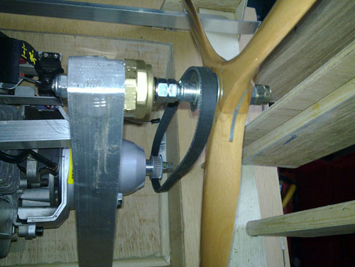
So a new pair of pulleys and belt were ordered to the perfect length to eliminate the need for the tensioner.
The reason I was trying to use the original config was space, the original drive belt is only 9mm wide, and althought the new pulleys and belt are only 15mm, it was all a bit tight. But needs must and here the little beauties are.
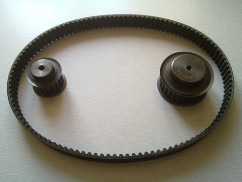
To get the belt length spot on I varied the pulley sizes until I got a match on a belt that could be supplied.
I ended up with a 28 tooth for the engine output shaft and 18 teeth on the proppeller shaft.
This gives me a slightly smaller ratio with only 12,444 revs instead of 12,800 (3% drop) but I should still have enough.....
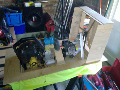
The change to a single deck V shaped hull means a new method of air delivery to the skirt and hull is required. Hull 1 relied on the void between the upper and lower decks to route the air to the skirt. Hull 2 needs a different method.
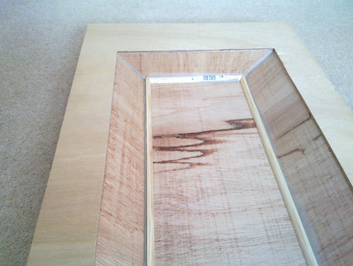
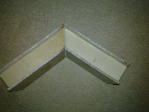
The change in design also offers an opportunity to increase the bag inflation by angling the air take-offs. Two box sections were made and glued together. The exit pipe was a simple mitre job to get to the correct shape.
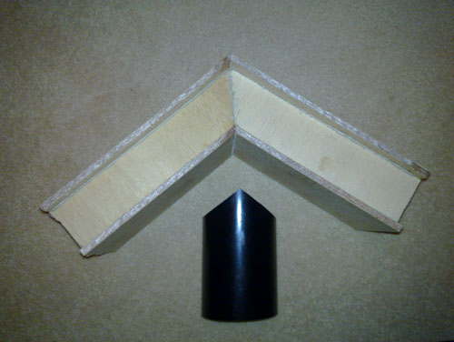
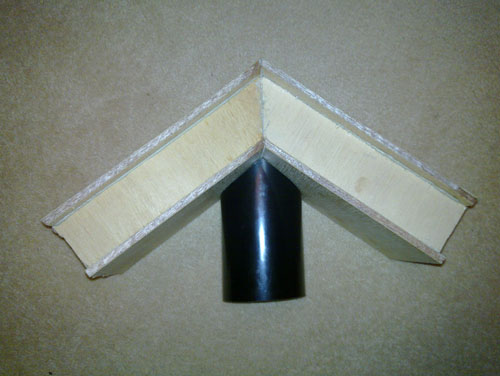
The delivery pipe was more complex. The space envelope for the lift engine and air pipe is now smaller. Moving the lift engine into the V of the hull, moved it back towards the centre of the craft. This has resulted in a 'self built' air tube rather that using pre-manufactured elbows.
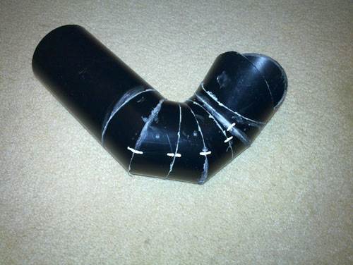
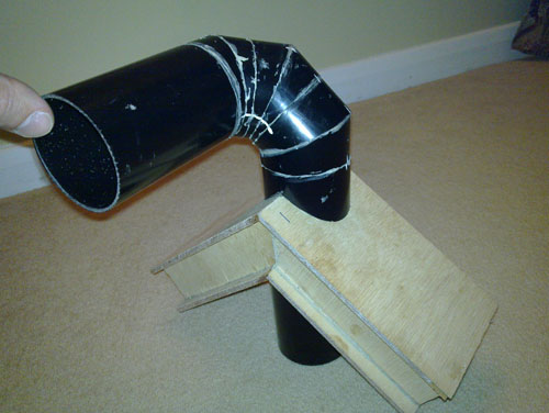
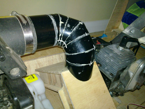
I am particularly pleased with the result of the air tube, compact and beautiful at the same time.
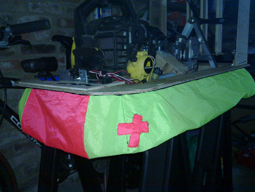
One lesson from the Hull 1 trial is that these things are going to be a complete arse to control. During any race it will quickly be difficult to see your own craft let alone steer accurately. With this in mind I have made a new skirt.
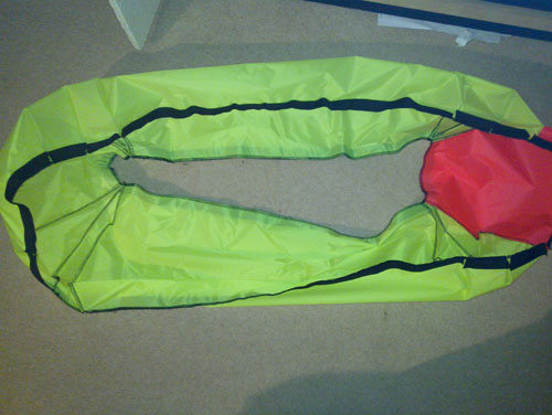
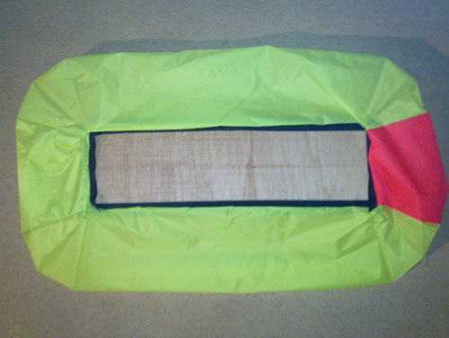
This new high visibility skirt will allow ne to pick my craft out from the crowd and the orange stripe will tell me where the front is.
Genius !